My second 3D development piece is a cabinet from a Fine Art studio. Like the Iron in the last 3D Development blog post was given to me by a random number that I was given to an object with the same number attached to it.
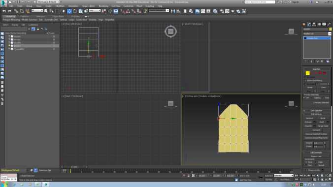
In the images above, you can see I started with a box, tried to get the cabinet as close as possible to the proportion and scale of the live object, and extruded the front face in revealing a rectangle with a hole in it. In the second example, you see I have made one flat rectangle with the same box tool, and duplicated the first (on the top) and placed the last two underneath one another.

In this screenshot, I used the bevel tool to make the top of the cabinet expand and shrink the top face in order to show the result that is found on the image of the object in question.


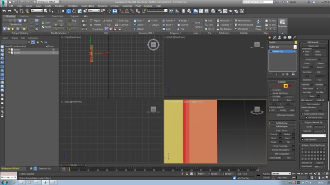
As I went on, I kept adding each individual the objects found from the live images, one by one and duplicated them where they shown great quantity from the images I took before modelling.
The first image shows a box with a piece of paper sticking out of it. This was done by making a rectangle out of a box, where I used a shell modifier and extruded the face on one of the sides inwards to get the hole in the middle. To make the flap at the front, I extruded the line connected to where I pushed the front face. I made the paper by making a plain from the plain tool and gave it about 5 width and heights segments and manipulated the vertexes within that shape and then repositioned it, into the box. To make the tubes in the second image, I used a cylinder, bent one of the sides, and kept the other side the same. This was a process of moving lines and vertexes around. I then made the caps separate, where I made a cylinder and bevelled the top face three times, to get an elevation and create the shape that appears on the actual model I copied it from.

Here is what the 3D Representation of the cabinet looks like with all of its contents.

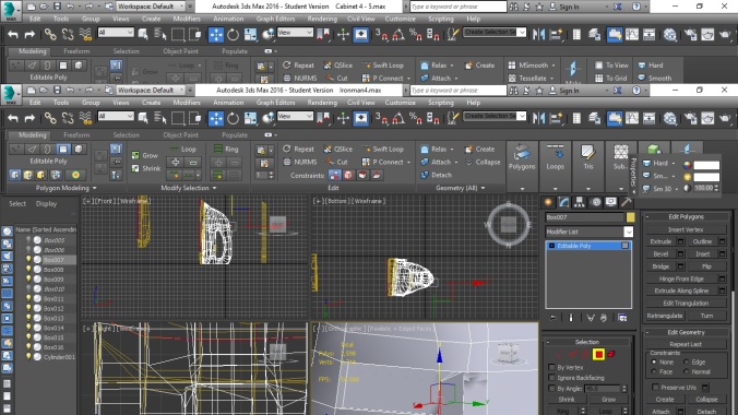
After the most time consuming part of the this development process, I went into more detail and added the hinges that adds the realistic look to it. I started by adding the outer cylinder by using the cylinder tool, where I added the lines with a Swift Loop and extrude them inwards to add depth.
The second image shows the inside of the cabinet where we see how the hinge mechanism works, but this design is purely estimation, as I couldn’t get a good look at the object as I couldn’t disturb it.
The hinge was create by using the plain tool to make a flat surface, where I just manipulated the vertexes, in order to bend the plain and get this result.


The first image in this stage of the 3d development process, we see the bolt lock that connects to the left cabinet door. It was made by manipulating the verts from a standard plain, where I added one cylinder, used the bevel tool to expand the top face and shrink it. Which were then duplicate seven times across the manipulated plain.
The second example shows the pad love, which connects to the opposite door of the bolt lock. This was made from a simple box that was beveled on the top and bottom, where I also added a cylinder by using the line tool, create a circle, highlight the bent line (made earlier) navigated to the compound primitive tab; loft tool; select the circle; revealing the metal pipe to be attached to the padlock base. This was achieved by positioning the cylinder over the lock, right click with it highlighted and scroll to Attach. This shown the complete padlock, after I changed the positioning of the vertexes to completely copy from the live image.
The plain that is attached to the padlock was made by a simple plain, where I used the Cut tool (shown on the toolbar ribbon as a pair of scissors) to delete a rectangular shape within the middle of the plain. The plain was then Attached to the door of the cabinet and the vert’s positioned to make the bent look that was shown in the live image above.
The third image shows the handle of the door underneath the padlock. It was created with a plain to start with, where I Attached a cylinder that was beveled, and the face was deleted to correct the topology.
That’s all of the cabinet and its assets made and here is the end result:


To make the rendered image, I modified the render settings that included an output size as a HDTV (video) and assigned the material to the renderer as a mental ray.
Reflection:
I feel and think that I have not missed a single detail within this model and the smaller models, a part of the larger model in question.
At some point before the second semester, I will be texturing this model, in order to achieve higher potential with this model.